- TIE-0240x
- 6. Dynamic Binding and Ownership of Objects
- 6.6 Drawing in Qt
Drawing in Qt
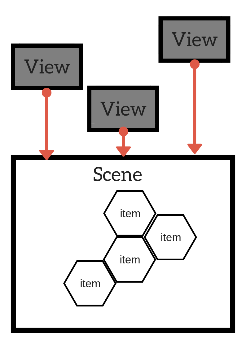
Qt’s Graphics View offers a way to manage and handle a large set of programmer defined graphical elements. The Graphics View architecture consits of a scene represented by a class QGraphicsScene and the items represented with subclasses of QGraphicsItem. The scene and its elements are made visible to the user by showing them in a view defined by QGraphicsView. One scene can be viewed through several views.
QGraphicsScene
The role of QGraphicsScene is to act as a container to a collection of graphical elements. It’s responsibilities include:
- offering a fast interface to manage a large set of elements
- propagating events to each element
- managing item state e.g. selection and focus
The scene acts as a cointainer to elements, which are objects of the type QGraphicsItem. An element can be added to a scene by calling QGraphicsScene::addItem().
QGraphicsScene* scene = new QGraphicsScene;
QGraphicsItem* item = new QGraphicsSimpleTextItem( "hei!" );
scene->addItem( item );
Qtoffers a wide range of preimplemented elements such as QGraphicsLineItem, QGraphicsPixmapItem and QGraphicsSimpleTextItem. New elements can be created by deriving from QGraphicsItem:
class MunItem : public QGraphicsItem
{
   public:
       MunItem( QGraphicsItem *parent = nullptr);
       void paint(QPainter *painter,
                  const QStyleOptionGraphicsItem *option,
                  QWidget *widget = nullptr);
       QRectF boundingRect() const;
   private:
       ...

};
IT is usually necessary to implement a paint function paint() to programmer defined elements. Similarly a bounding rectangle for the outer limits of the elements is defined by implementing boundingRect(). This is used to decide if the element needs to be redrawn. In addition, an element can have a separately defined shape shape(). However, the bounding rectangle is always a rectangle.
QGraphicsView
QGraphicsView is a widget that shows the contents of a scene. There can be more than one view to a single scene. The view receives events from the keyboard and the mouse, converts them into events for the scene and sends the events to the scene shows. The following code creates a scene and a view and sets the view to show the contents of a scene. In addition, it also sets the range of the scene:
QGraphicsScene* scene = new QGraphicsScene;
QGraphicsView* view_ = new QGraphicsView(this);
view_->setScene(scene);
scene->setSceneRect(0, 0, 600, 600);
QGraphicsItem
The base class QGraphicsItem is the base class for all elements drawn into the scene. As already noted, typical shapes are available as predefined elements. Deriving from the base class it is possible to define own elements. QGraphicsItem makes it possible to:
- Handle mouse events
- Handle keyboard events
- Drag and drop
- Grouping elements by either setting one element as a child of another element or by using
QGraphicsItemGroup. This is useful when there is a need to handle a group of elements as a whole. - Collision detection with the help of functions
shape()andcollidesWith(). The simplest way to implement collision detection is to implement theshape()of the element so that is returns the exact shape of the element. ThenQGraphicsItemhandles collision detection.
Coordinate System
Graphics View is based on the carthesian coordinate system. The location of an element in a scene is defined by its X and Y coordinates. According to Qt’s coordinate system the X-axis grows from left to right and the Y-axis top down. Hence the starting point 0,0 is locates in the left upper corner.
In practice there are three coordinate systems in use, one for each part. There are element coordinates, scene coordinates and view coordinates. View coordinates are coordinates of QGraphicsView. Scene coordinates are coordinates that define the location of the elements inside a scene. Each element further has its own coordinates where 0,0 marks the centerpoint of the element. The element coordinates matter when creating own elements as for example mouse click event locations are based on them. Also the bounding rectangle and the shape are defined in element coordinates.
The scene defines a coordinate system for all elements in the scene. It desribes the location of each of the top level elements and creates the basis of propagating events in the scene to the elements. Each element has a location in the scene as well as the bounding rectangle, i.e. scenePos(), sceneBoundingRect(). These decribe the element location in scene coordinates and the area with which it is determined which areas in the scene have changed.
Vuew coordinates are the coordinates used in the view widget. The scene shown does not affect this coordinate system. The left upper corner is always 0,0 and right lower corner is width, height. All mouse events and drag&drop events are received in view coordinates and need to be transformed into the scene to interact with elements.
